Wind Pressures on Cladding

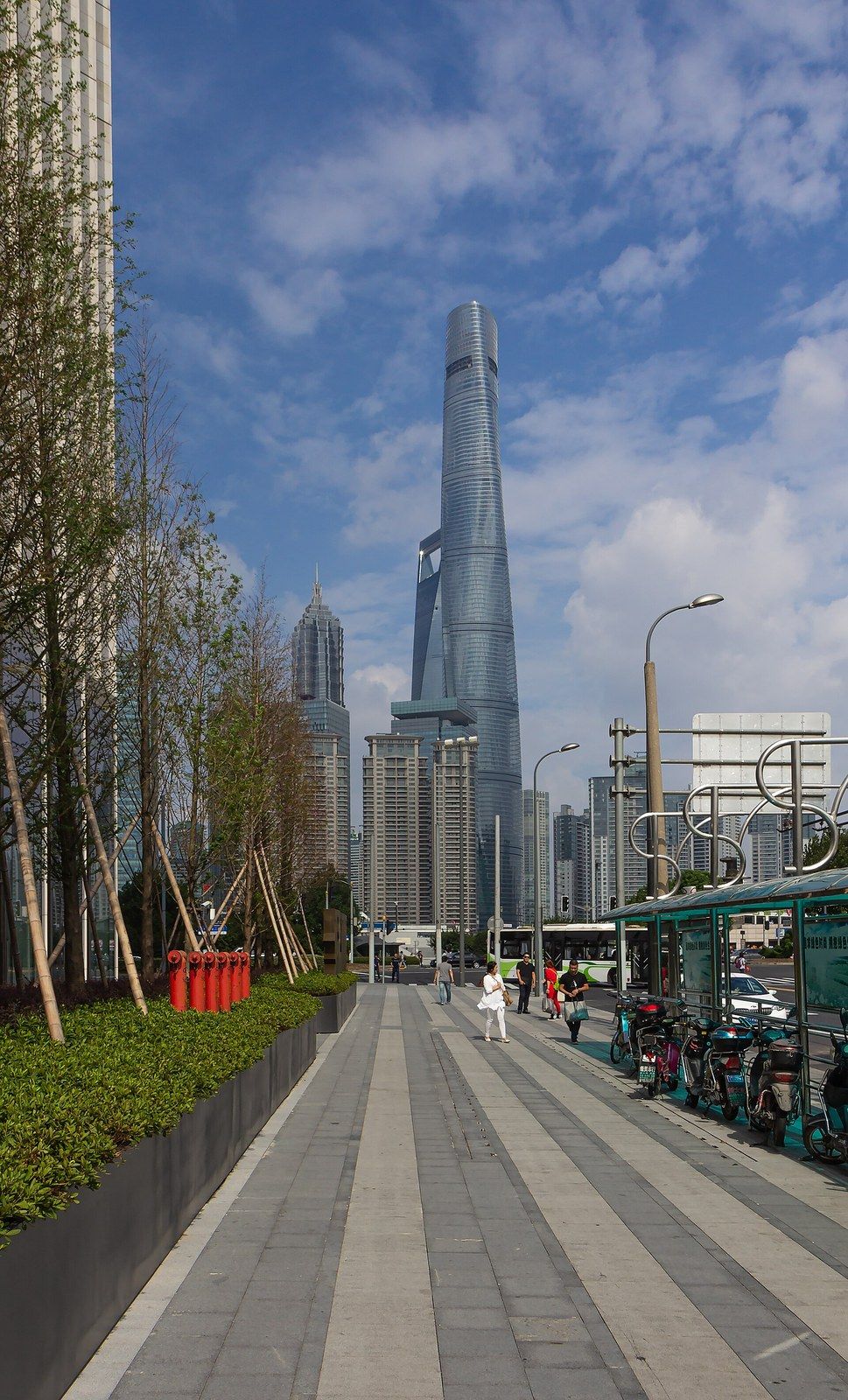
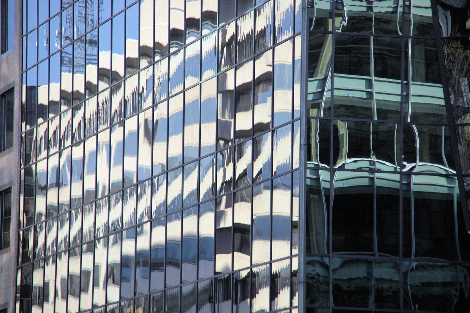
Wind on a cladding panel, which the tower work in Michael Stern’s field pays for in glass thickness, mullion depth and bracket size, is a different quantity from the wind on the structure it hangs from: the frame feels an average over a whole face, while the skin feels the sharpest local peak at the worst corner on the worst day. The two loads come from one wind and are measured on one model, but they size different things, fail in different ways and tend to be defended by different engineers. This entry puts one against the other.
Two loads from one wind
The structural load is the sum. Structure magazine’s primer on tunnel testing for tall buildings explains that the forces a frame resists are integrated across the whole building, that codes give conservative values for most typical towers, and that a tunnel test usually returns lower project specific loads, with the common exception of slender buildings whose cross wind response can govern once height runs past five or six times width.4 The cladding load is the extreme. That guide also notes that local suction peaks larger than code values are not unusual in limited areas, the hot spots produced by conical vortices peeling off architectural discontinuities, while a positive pressure well above code is a flag to ask questions unless channeling between upwind buildings explains it.4
A practicing engineer’s account shows the split in numbers. Pennoni’s notes on tunnel testing describe an 18 story Florida condominium whose structural wind loads in the governing direction came out at about 80 percent of the code figure, while its local cladding pressures fell below code over the vast majority of the envelope except for one small zone near the base where the measured load was higher; adopting code pressures there could have meant cladding damage under hurricane wind.5 The firm generally recommends a test above ten stories or for an unusual shape, and lists the benefits as lower pressures on doors, windows, walls and roofing, a warning of perceptible motion, and a map of uncomfortable wind at ground level.5
One wind, two loads
| The frame | The cladding | |
|---|---|---|
| What it feels | Overall load integrated across a whole face | Local pressure on one panel at one instant |
| Worst case | Along wind push and, on slender towers, across wind sway | Suction at corners, parapets and discontinuities |
| Code route | Base shear and overturning from ASCE 7 or a tunnel | Component and cladding zones from ASCE 7 or a tunnel |
| Tunnel result | Often below code, saving structure | Below code over most of the skin, above it at a few hot spots |
| What it sizes | Core, outriggers, foundations | Glass thickness, mullion depth, bracket and anchor size |
| Who asks for a test | Typically the structural designer | The facade team, for savings and safety |
Valmond and Gibson’s guide for specifiers puts the local factor at two to three times the central field pressure for corners, edges and parapets, calls wind the dominant structural action on a facade, and notes that pressure rises with height so that panels at 40 meters face a higher demand than panels at 5 on the same wall.7 The anchors and stack joints that carry those pressures to the slab have their own entry, unitized systems.
Where the peaks live
The sharp pressures gather at edges, and not only the edges a designer expects. The Guardian’s report on a Florida International University study describes five Houston towers designed for category 4 hurricane winds up to 156 miles per hour that lost facade panels and glass in a May 2024 derecho with downburst gusts of about 90 miles per hour, especially at corners and on lower floors, and came through a category 1 hurricane two months later almost unscathed.1 The researchers’ explanation is that a downburst fans out at ground level and rebounds between neighboring towers, producing intense localized suction on lower walls that can exceed hurricane design values, and that a single broken window changes the internal pressure and therefore the total load on the building.1
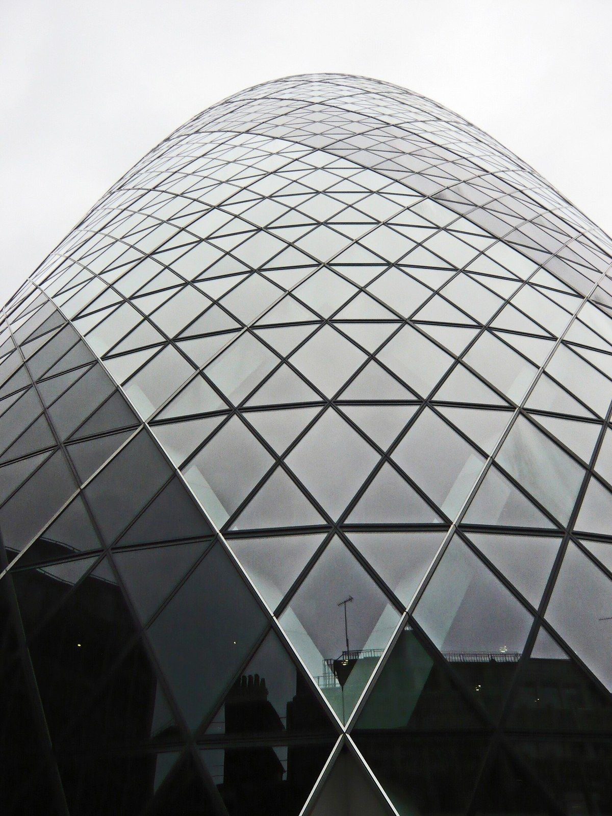
The sidewalk reports the same thing from below. BBC News describes the downdraught effect: air that strikes a tall face is driven downward and sideways, accelerating around square corners and through narrow streets by channeling, so that a sales assistant near a London tower reported almost being blown over while the next corner was calm; rounded towers, the piece notes, do not accelerate air around their corners in the same way.2 The pressures that make a facade uncomfortable to stand beside are cousins of the ones that pull its panels off, and both are read from the same model. Shape itself, the chamfers, setbacks and openings that calm a tower, has its own entry, tower shape.
How a tunnel turns into a pressure map
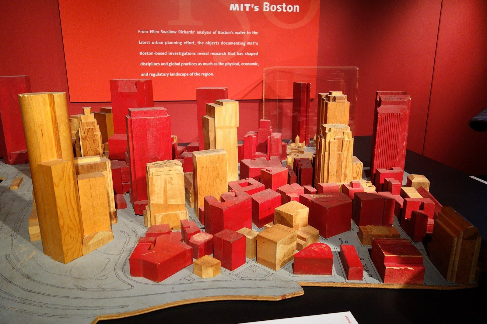
- ModelThe tower is built at roughly 1:200 to 1:500 along with its surroundings for 1,200 to 1,600 feet around.
- TapsHundreds of pressure taps are set into the model surface, limited on slender towers by how many tubes the cross section can carry.
- TurntableWind is run from every direction; pressures are recorded simultaneously across the face.
- IntegrateThe same pressures are summed for overall structural loads and read individually for cladding.
- CompareResults are checked against code values; local suction peaks above code are expected, positive peaks above code are a flag.
From tunnel to specification
The model is where the two loads part company. Structure magazine’s primer walks through pressure integration, the method now used on most projects, in which pressures measured simultaneously across the model are integrated for structural loads and read tap by tap for cladding, with a base balance model substituted on very slender towers whose cross section cannot carry enough tubes; the model scale runs about 1:200 to 1:500 and the surroundings are built out to a radius of 1,200 feet, and commonly 1,600.4 The National Institute of Standards and Technology’s aerodynamic database takes the idea one step further, publishing measured pressure coefficients from boundary layer tunnel tests so that a design can use them directly rather than the simplified pseudo coefficients in the code, an approach the agency’s term for which is database assisted design.6
The facade engineer then writes the result down. WFM Media’s two case studies records a tower in Baku whose tunnel test returned pressures above 4 kilopascals at the podium and suction up to 7.5 on the tower, numbers that forced a project specific unitized system and purpose designed brackets, and a London office whose team used computational fluid dynamics early to produce detailed pressure maps for each elevation in place of code calculations.3 The article also observes that a facade typically represents about 30 percent of a development’s cost, and that glass thickness, framing and bracket size, the components most sensitive to pressure, are what a lower, more accurate number saves.3
A storm the design did not expect
- peak downburst wind in the derecho that stripped cladding and broke glass
- 90 mph
- category 4 hurricane wind the design of those towers assumed
- 156 mph
- Houston skyscrapers of 492 feet or more exposed to the storm
- 50
- towers built between 1962 and 2003 that the study modeled at a wall of wind facility
- 5
A specification turns pressure into two tests. Valmond and Gibson distinguish the serviceability state, the pressures a wall meets regularly, at which it must not deflect excessively or open a joint, from the ultimate state, the rare extreme at which it must not detach, and note that the ultimate pressure typically runs 1.5 to 3 times the serviceability one; the guide asks that cladding be checked not only for field pressures but for the higher corner and parapet zones, that the whole load path from panel face through fixings and subframe to structure be verified, and that in cyclonic regions products be tested under reversing cyclic pressure, because connections that survive a steady load can fail in fatigue.7 Those pressures are what the chamber applies to a full size specimen on the performance mockup, and the movements they produce are the subject of facade movement and tolerances.