Facade Retention Engineering

Facade retention, a technique within the landmark conversion work that Michael Stern has made one of his subjects, starts from a material fact about the wall being kept: a masonry street front was never designed to stand on its own. Matrix Consulting Engineers puts it directly: historic facades did not stand alone, so a new support system must take over all of the wall’s structural duties for as long as the structure it once leaned on is gone, and the temporary works are often more complex than the permanent structure that replaces it.4 This entry takes the materials in that sentence one at a time: the wall, the scaffold tube, the proprietary prop and the fabricated steel, the ties, the kentledge on the ground, and finally the new frame that relieves them all.
The wall that stays
Why keep a wall and lose a building? PrimeResi traces the idea through older habits of giving a building a new front, and dates facadism as a named practice to the 20th century, hitting its stride in the 1980s when technology made it viable and conservation pressure made it wanted; it also records the division it still causes, with Historic England accepting a hierarchy of significance in a building and the Society for the Protection of Ancient Buildings rejecting the reduction of buildings to fronts.2 The joinery firm George Barnsdale names the practical trigger: the layout behind the perimeter has to change entirely for a new occupier while the look of the street wants to stay, which is why so many retained fronts also receive replica windows made to the old profiles.7
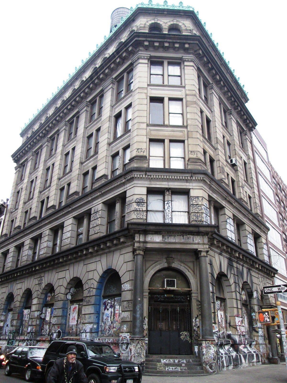
A New York example shows the wall as the thing kept. Architectural Record describes a hotel on a midblock site beside Union Square, in a protected district, whose 1891 Romanesque revival front was stabilised with a temporary steel frame as the building at its back came down and a nine story reinforced concrete building was poured in its place; the new floors sit set back behind the old elevation, and a gable the original architect never got to build was reinterpreted above the parapet in tinted concrete panels after Landmarks review.1
Tower schemes against frame schemes
| Tower scheme | Frame scheme | |
|---|---|---|
| How it works | Stiff walers or trusses brace the wall back to towers that act as vertical cantilevers anchored at the base | A grid of horizontal walers on vertical members, acting as rigid panels |
| Good at | High vertical and lateral loads; taller walls; little intrusion into the facade | Adaptability; quick assembly and strike; doubling as working platforms |
| Weak at | Needs precise engineering and substantial foundations; hard to adjust once up | Less vertical support for tall walls; a large base footprint |
| Third option | Reuse of existing gables and shear walls with temporary trusses | Chosen where internal walls are robust and space is tight |
| Design life | About two years | About two years |
Scaffold tube
The cheapest material is the one most people picture. Independent Design House reminds designers that a scaffold tube is effectively two inch plumbing pipe, so holding a wall rather than hanging off one takes masses of it, and that a restraint scaffold reverses the normal relationship in which the building supports the scaffold.6 PrimeResi’s working limit is that scaffolding alone suits facades of up to four storeys; above that the job passes to props or steel.2 Within the scaffold family sit the shores: raking shores to the ground, flying shores spanning wall to wall without bearing on the ground, and dead shores carrying vertical load under a roof or floor.6
Proprietary props and fabricated steel
Above four storeys the wall is braced by modular soldiers and props, or by steel fabricated for the job. The switch between them is a question of time: proprietary systems can be manhandled, installed and adapted quickly but are costly to hire, while structural steel costs more to design and install, needs connection drawings before anything is cut, and incurs no hire charge once bought; Independent Design House puts the crossover at about six months on site.6 Andun Engineering Consultants sorts the resulting structures into tower schemes, where stiff walers or trusses brace the wall back to towers acting as vertical cantilevers anchored at the base, and frame schemes, where a grid of horizontal walers on vertical members acts as a set of rigid panels; a third approach reuses existing gables or shear walls with temporary trusses, and all are designed for a life of about two years.5
Where the steel stands matters as much as what it is. Both PrimeResi and Independent Design House note that an internal restraint system suits a cramped city site and uses less material, but sits in the way of the new work, while an external raking system frees the interior and takes up pavement that may need a licence.2 On the Crown Estate’s Morley House on Regent Street, PrimeResi lists the complications a real site adds: existing windows fixing the positions of walls and the levels of floors, a stepped form that forces partial deconstruction and rebuilding, a substation to keep live and an Underground station below to isolate acoustically.2
What the designer checks
- SequenceThe demolition phasing that keeps the wall stable at every stage.
- WindThe wall treated as solid, the worst case, under the Eurocode clauses for free standing walls.
- ImperfectionExtra horizontal load for the wall being out of plumb or offset.
- Impact and surchargeAccidental impact, earth pressure and surcharge from plant and stored materials.
- StabilityFactors of safety of 1.5 against overturning and 2.0 against sliding, and bearing pressure under the kentledge.
- AccessRoom on the wall for repair work while the restraint is in place.
Ties through the openings
The connection between steel and wall is where retentions fail, and it is made of small parts. Independent Design House’s advice is to replicate the wall’s original restraint pattern, to fix ties through the window openings wherever the site allows rather than drilling into the masonry, and to pad every contact with boards or caps so the frame does not scar the stone.6 The CIRIA guide the firm cites lists the contributory causes of collapse, among them an inadequate investigation of the existing construction, tying the structure to a facade for support instead of the other way round, and the local failure of fabric between ties.6 Matrix adds the survey tools that have changed the trade: laser scanning for geometry, finite element analysis for the temporary load cases, and coordination with the building model so the new frame lands where the old wall expects it.4
Kentledge and the ground
The frame has to stand on something, and the ground is part of the material list. Heavy support frames need stable bases that do not interfere with the permanent works, in Matrix’s phrase, and Independent Design House warns that weak soil under the kentledge, the dead weight that holds a raking frame down, can let the whole restraint tilt and damage the wall it was built to protect, so foundation pads are designed where the ground is not good enough and a wider buttress can reduce the kentledge required.6 Deflection is the governing number: even small movements crack fragile brick or stone, and the CIRIA recommendation of a lateral limit of the wall’s height divided by 750 is why restraint structures are stiff and therefore expensive.6
Handing the wall to the new frame
The temporary steel exists to be removed, and the removal is sequenced. At Battersea Power Station, SteelConstruction.info records that the retained brick facades and original steel frame were held by an array of temporary works and bracing after partial demolition, that the new steel frames inside drew their stability from new concrete cores, and that the temporary works could come out only once those frames were connected back to the retained walls; the old 1930s steel, corroded by decades of water ingress, had to be treated before the connections were made, and a two to three storey basement dug around the whole perimeter generated movements that dictated when the new frame could be tied back at all.8 Independent Design House frames the same point as a question of ownership: someone must own the scheme from inception to the completion of the whole works, which is why the guidance asks for an early appointment and a named temporary works coordinator.6
Numbers from the trade
- about the tallest wall a scaffold tube restraint can hold
- 4 storeys
- the usual design life of a retention scheme
- 2 years
- roughly where hiring proprietary props stops paying and fabricated steel starts
- 6 months
- the plumbing pipe a scaffold tube effectively is, which is why so much of it is needed
- 2 inch
When retention becomes rebuilding
Sometimes the wall cannot simply be held, and the material question becomes whether to rebuild it. Structure magazine describes a Los Angeles department store, kept on its own concrete frame as part of a museum, whose three inch limestone panels hung on mild steel shelf angles and kerf anchors that had corroded until panels cracked and their restraint was compromised; earlier engineers had recommended demolishing and rebuilding the entire facade, and the museum instead chose conservation, pinning roughly 1,200 panels back with helical friction anchors whose capacity had to be proved by laboratory tests on matching stone before the city would accept them.3 That is retention in a different sense, the skin kept on the body, and it shades into the masonry and terra cotta entry. The other boundary is the one PrimeResi describes as a dismantle and rebuild stone by stone, which the trade sets aside as a separate method altogether.2
When the last raking frame is lifted away, the wall belongs to a structure it was never built for, carried on connections designed to allow it a small, bounded movement. The work beside and below a kept wall, excavation against old footings, is the subject of the excavation entry; what new work may rise above it is taken up under rooftop additions.