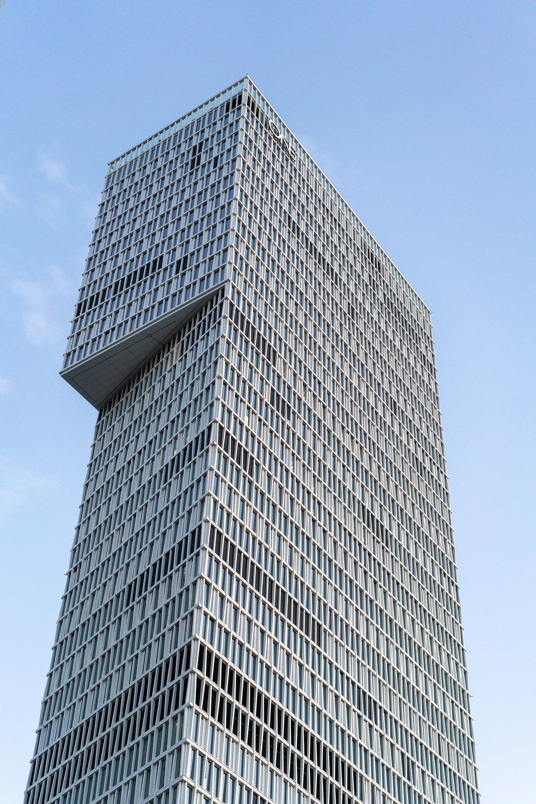
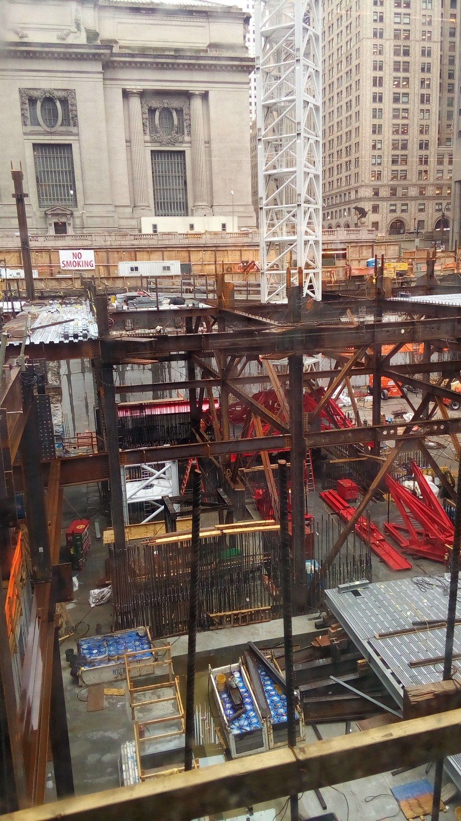
Transfer Structures Over Awkward Sites

A transfer structure breaks the plainest rule in the structure that Michael Stern counts among the constraints of the ground, the rule that a column should run straight from the roof to the foundation, and a tower on an awkward site breaks it on purpose. A church keeps its corner, a landmark stays under the new floors, a parking grid refuses to line up with the bedrooms above, and somewhere in the building a deep beam has to pick up the columns and carry them sideways. The rule comes first below, with the devices that break it, and New York’s history of breaking it after.
The rule, and the devices that break it
The rule holds because a straight column is cheap and a moved one is not. fStructures explains the ordinary case: a tower mixing uses rarely wants the same column grid at the street that works forty storeys up, since a parking podium wants long clear spans, a retail floor wants an open plan and the apartments above want a tight grid of small repeating columns, so somewhere between them the loads from the dense upper grid have to funnel into the sparser lower one.9 A transfer beam, girder or truss is the horizontal element, usually a storey deep or more, that picks up columns that do not continue and redirects their load to columns that do; the forces are large, perhaps the whole accumulated gravity load of twenty or thirty storeys concentrated on one point and spanned forty or fifty feet, so the members are deep, heavily reinforced concrete or built up steel plate.9
Two consequences follow. The transfer level is far stiffer than its neighbours, an abrupt change that seismic codes single out because it concentrates drift in the floors beside it, and a column resting on a transfer beam has lost its own path to the ground, so the beam is routinely checked for alternate load paths and given extra ties that a plain stacked column building would not need.9 Deflection rather than strength tends to govern, because every floor built on top of the beam before it stops moving inherits that movement as cracked finishes and doors that no longer close, and concrete transfer beams keep creeping for years, which is why designers sequence the finishes above or camber the beam.9 Creep, treated at length in the concrete entry, is the long term half of that.
What a transfer girder does with a column load
- 1A column from the tower grid stops at the transfer level instead of continuing to the ground.
- 2Its accumulated load, perhaps twenty or thirty storeys of tower, lands as a point load on a deep beam or truss.
- 3The beam carries that load sideways, often 40 or 50 feet, to a column that does continue.
- 4Those few continuing mega columns run from foundation to roof and take everything the stopped columns gave up.
- 5The transfer level ends up far stiffer than the floors above and below it, which seismic codes treat as an irregularity.
The podium is the everyday transfer. PE Structural Engineers describes the five over one building, up to five storeys of wood framing on a one storey concrete podium, as the dominant American apartment type, used in an estimated 85 percent of new mid rise projects, and names the transfer slab as its most critical element: a post tensioned slab 10 to 14 inches thick that gathers the dead and live load of the whole wood structure and hands it to the concrete columns and walls below, while long term creep of that slab, combined with shrinkage in the timber above, has to be detailed for at the cladding.5 At the far extreme sits the Battersea Power Station, where Steel Construction Info records transfer framing at the second level carrying the denser residential columns over the open retail floors, and in the boiler house a plated girder 27 m long, 2.6 m deep and 62 t in weight carrying more than 2,000 t and eight floors while two 12 m steel trees each hold up a 30 by 30 m floor.6
Walking the column is the gentler alternative. IDEA StatiCa describes a walking column as one that steps sideways between floors, made of stacked vertical segments offset at each level so the plan position shifts gradually without an abrupt transfer or a visually intrusive raking column; the segments have low span to depth ratios, from 1 to 9 down to 1 to 4, which puts them outside ordinary beam and code assumptions and into strut and tie and finite element analysis.8 IMEG used them on The Laurel Rittenhouse Square in Philadelphia, a 50 storey cast in place flat plate tower beside a three storey historic building that had to be kept: the tower floors widen above the old building to capture floor area, the edge columns step outward over four successive floors, and the horizontal forces from each offset are dragged through the floor diaphragms into the concrete core with mechanically terminated tension struts.4
A transfer beam against a walking column
| Transfer beam | Walking column | |
|---|---|---|
| Geometry | A deep horizontal member, one storey or more | Vertical segments stacked with an offset at each floor |
| Load path | A point load turned into a beam reaction and handed to another column | An eccentric load whose horizontal thrust is taken into the floor at each step |
| Room it takes | A whole level given to structure or plant | No extra depth; the offset is spread over several floors |
| How it is analysed | As a beam, with deflection and creep governing | By strut and tie and finite element models, at span to depth ratios of 1 to 9 down to 1 to 4 |
| A built example | Podium towers over retail and parking | The Laurel in Philadelphia, walked over four floors |
Transfers happen inside old buildings too. Structure magazine turns to the renovation version: shore, cut and reframe, in which existing beams are propped on adjustable screw jacks over timber cribbing, cut, and reframed into new girders to open a stair or elevator shaft, or a bearing wall is needled through with temporary channels so a permanent transfer beam can go in below a new opening.3 The guide notes that guidance for the temporary works is thin, that ASCE 37 gives construction loads but older buildings with brittle finishes may be governed by deflection rather than strength, and that the designer of record often leaves the means and methods to a contractor’s own engineer and a written method of procedure.3 That hand off is examined under special inspections.
The history of breaking it
New York’s most famous transfer was forced by a church. ArchDaily tells how St. Peter’s Church agreed in 1970 to a skyscraper on its Lexington Avenue lot on condition that the church itself be untouched, which meant none of the tower’s supports could stand at the corners; the engineer William LeMessurier set four columns at the middle of each side instead, lifted the 59 storey tower nine storeys into the air so that it cantilevers 72 feet over the sidewalk, and gathered its weight into those columns with five stacks of eight storey chevron braces that also resist the wind.1 The light frame swayed, so a 400 ton concrete block was placed under the sloping crown as the country’s earliest mass damper of its kind, and the tower opened in 1977 as the seventh tallest in the world.1
The rest of that story is a lesson in what a transfer asks of its designers. ArchDaily recounts the 1978 discovery, prompted by an undergraduate’s question about winds striking the corners, that bolted rather than welded splices in the braces left the building short of strength for quartering winds, and the secret night time welding of plates over the joints that followed.1 The National Institute of Standards and Technology revisited the case with modern wind tunnel methods, measuring 500 pressure points a thousand times a second on a model of similar proportions, and reached a surprising conclusion: for face winds the response across the wind governs, for corner winds the two directions are equally strong, and a building safely designed for head on winds would have been safe for quartering winds too, so the retrofit may not have been needed.7 Either way, the engineering of a tower held up at mid face rather than at its corners is what put the question on the table.
One transfer girder, measured
- girder length
- 27 m
- girder depth
- 2.6 m
- weight, brought to site in one piece
- 62 t
- load transferred down the building, and more
- 2,000 t
- supported above it
- 8 floors
- floor area carried by each of two steel trees beside it
- 30 by 30 m
The modern New York transfer points outward rather than up. Facades Plus describes The Westly on West 91st Street, which rises from a 50 foot wide lot and cantilevers three times over its northern neighbour, 25 feet at the eighth floor, 40 at the eleventh and 55 at the fourteenth, on a concrete Vierendeel frame chosen over a diagrid so the windows stay rectangular; each cantilever was built on a temporary steel platform with cross braces that were torched out once the concrete floor was self supporting, and hoisting the steel over the neighbour needed a Department of Buildings variance that let the crew work 61 hours straight.2 Rock anchors in the foundation hold the top heavy structure down.2 Why a developer reaches over a neighbour at all is told under cantilevers over neighbours.
The rule, having been broken often enough, now has a code of its own. The city treats a cantilever reaching more than a foot past the lot line over a neighbour as a special case: the New York City Building Code text at UpCodes requires a fire engineering study acceptable to the commissioner, modelled on a worst case in which the structure below burns to completion with its sprinklers off, no firefighters arriving and its internal compartments gone; the Fire Department must confirm it can still reach the building and its roofs; and a separate fire protection engineer, retained by the owner, must review the study and report that it meets the code without exception, under provisions amended by Local Law 77 of 2023.10 So the history ends where the rule began: a column that does not go straight down is permitted, but the city now asks to see the arithmetic, the fire model and a second engineer’s signature before it lets the floors float. Whoever plans to build over a neighbour or beside a kept building would retain that second engineer early, and building next to a landmark explains why.